On my on-going project in creating a tattoo concept for a friend of mine based on design from the game Destiny, I was asked how my workflow in Blender looks like. Fortunately, this time around I had decided to record my sessions and could piece together a summary of all the steps I’ve done up till this point. 3D-modelling is probably one of the funniest things I know to work with on my spare time so it would maybe be fun sharing not only the results but also the journey there.
I’ve also included some captions explaining a bit more about each step as I don’t feel it would be rather exciting hearing me ramble on about each and every decision I make in the process. I hope you enjoy it, I’m continuing on the rendering and finalizing this concept at the moment.
The shader reloader now supports time related buffers which enables me to animate textures and gradients on the fly in my shaders! In order to test it, I recreated the shader code from ShaderToy demonstrating Inigo Quilez palettes using Voyager: https://www.shadertoy.com/view/ll2GD3
I’m slowly becoming able to create more advanced shaders now that I have access to updated resolution and timestamp values from the Voyager engine. Next up on the horizon is to continue to stabilize the functionality I have today and make some necessary refactoring and cleanup. Hopefully I will be able to continue on improving the configuration settings making it easier for shader developers to set up their render passes and custom shader pipelines.
Quick little update this evening! Added support for off-screen rendering in Voyager which enables me to edit the final image composed by all previous render passes, such as adding a “twirl” effect for example.
I was also able to reuse the quad shader for the final render pass with my “Shaderset” configuration, enabling the user to configure their own shader pipelines. Shadersets specifies an array of shaders and attributes for a pipeline where shader types are based on their extension.
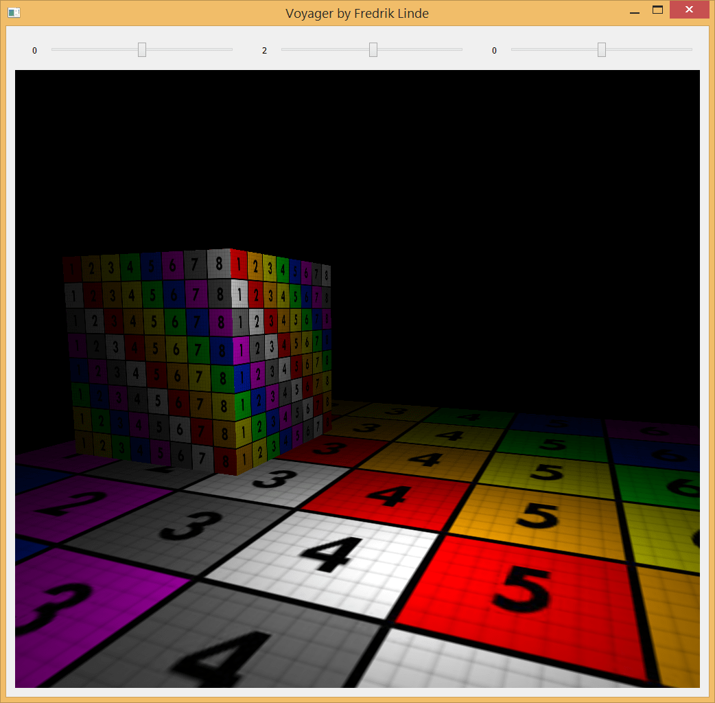
Well, it’s that time again. Nothing too fancy, just some fun hobby work I’ve been doing lately on my 3D rendering framework which goes by the working name “Voyager”. In this update, I’m trying it out by making this model viewer application. Can you guess which game this little bugger is from?
I’ve mostly been working on integrating the “Shader Reloader” I created last year into Voyager and the most recent feature I added was the support for wireframe shading. Instead of using geometry shaders which is the common approach, I sent barycentric coordinates as an extra attribute for each vertex and used edge detection by checking the fragment distance against the triangle coordinates with interpolation, essentially a similar approach as in a traditional ray/triangle intersection test.
Image courtesy of “Catlike Coding”
Although it’s cheaper, I have to think more about screen resolution and how I adapt the line thickness according to the camera distance (which looks awful by the way now at far distances and that’s why I’m not showing it…*nervous laughter*).
Anyway, having the shader reloading functionality implemented makes it so much easier to develop shaders as I’m saving plenty of time not having to recompile at every new startup of the model viewer application. The engine only supports an OpenGL render backend at the moment but I’ve established a high-level API agnostic interface which hopefully will help me implement DirectX backends in the future without too much pain. In the meantime while the interface grows, I’m focusing on more engine features and functionality that I want for creating effects and handling 3D-models.
(For the trained eye, please don’t kill me for the wireframe branch by the end of the shader, I will improve that check)
The next milestone for the shader reloader has been reached – today I was able to change simple shader code such as fragment color output while still keeping the application running.
The file notifier now publishes messages that any subscribers can pick up. Once a shader file is updated, the shader manager unpacks the message containing the information of the modified shader. If it is already present in the shader manager, it recompiles the shader and relink the active program. I have also taken inspiration from nlguillemot‘s implementation where the shader is identified using its file extension. Instead of naming it .glsl, it can be named .vert or .frag and then we automatically interpret its type when reading from disk.
Next up is more error handling, I would love to squeeze in more detailed output in the terminal. I still have SPIR-V compiled shader code as the final destination for this prototype, but first I’m going to tackle the next big problem which is managing uniforms between shader changes. Essentially, all I’m interested in is the main shader code and not the preamble. I could generate it on the fly given what OpenGL version the user wants to use (once again inspired by nlguillemot) and add it to the shader string when reading from disk. That way, I won’t have to rely on the targeted shader version…although it should be a detail to keep in mind, some shaders are probably targeted for a specific version with good reasons. I should do more research on this topic but for now, this is going pretty alright.
It took me a while to get started again after my long summer vacation, but now I am back at it again. I have spent the majority of September to learn more about OpenGL with my Voyager project and while it is not really anything impressive so far, I feel like the structure is better than any of my previous projects.
I created a geometry factory class to create all the geometries, which will later help me with loaded vertex data from other file formats. I also created a small renderer for OpenGL rendering – no hardcoded OpenGL vertex data setup. You load the geometry and put it in a renderable, then the renderer takes care of the rest. I am now primarily working on setting up more wrappers for OpenGL, preparing a debug shader to render surface normals and creating an obj loader.
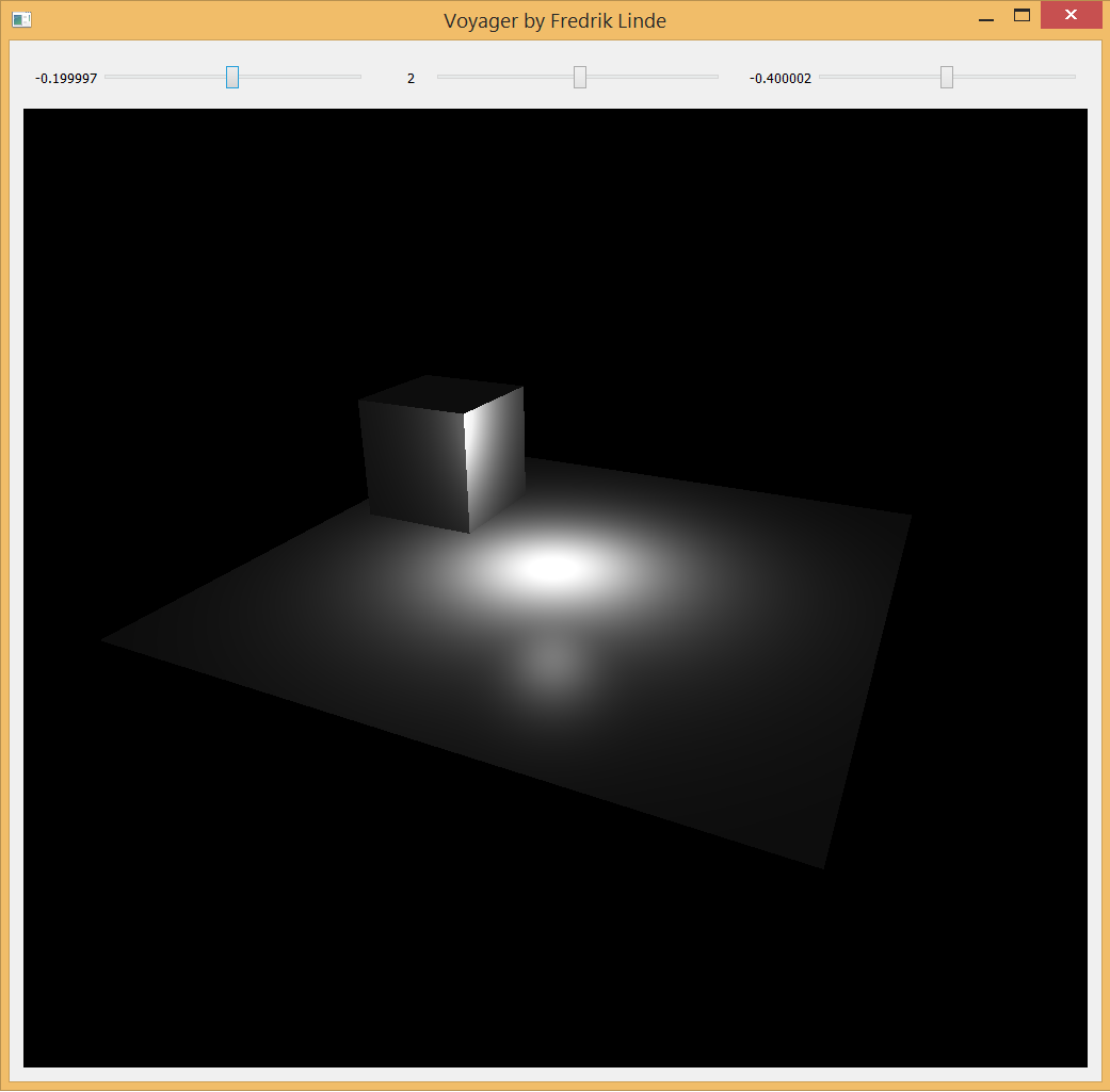
Last night was mostly focused on creating a default phong shader with light attenuation and as you can see, it is working quite decently. I read Light attenuation | I’m doing it wrong and highly recommend it if you have not read it already or are familiar with it. This post certainly helped me to understand the linear and quadric attenuation factors better, plus opening up my eyes on how much they are actually related to the physical world. Also, it is fully possible to plot it with Desmos as you read through it.
Qt also helps me a lot with window management and I am probably going to use it as the primary window management library throughout the project. For now I am just using sliders to adjust my one and only point light. I will give it some more friends later, I promise.
Check out my repository on Github and leave a comment if you have any thoughts. Feedback is also greatly appreciated 🙂
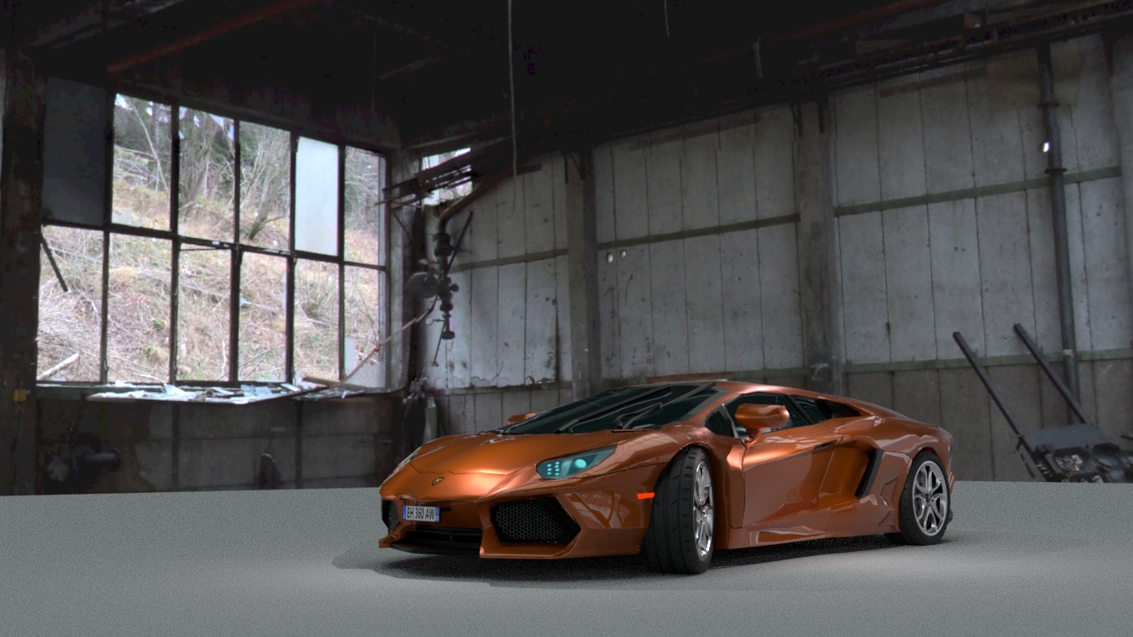
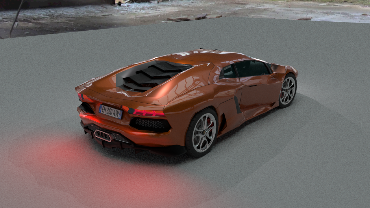
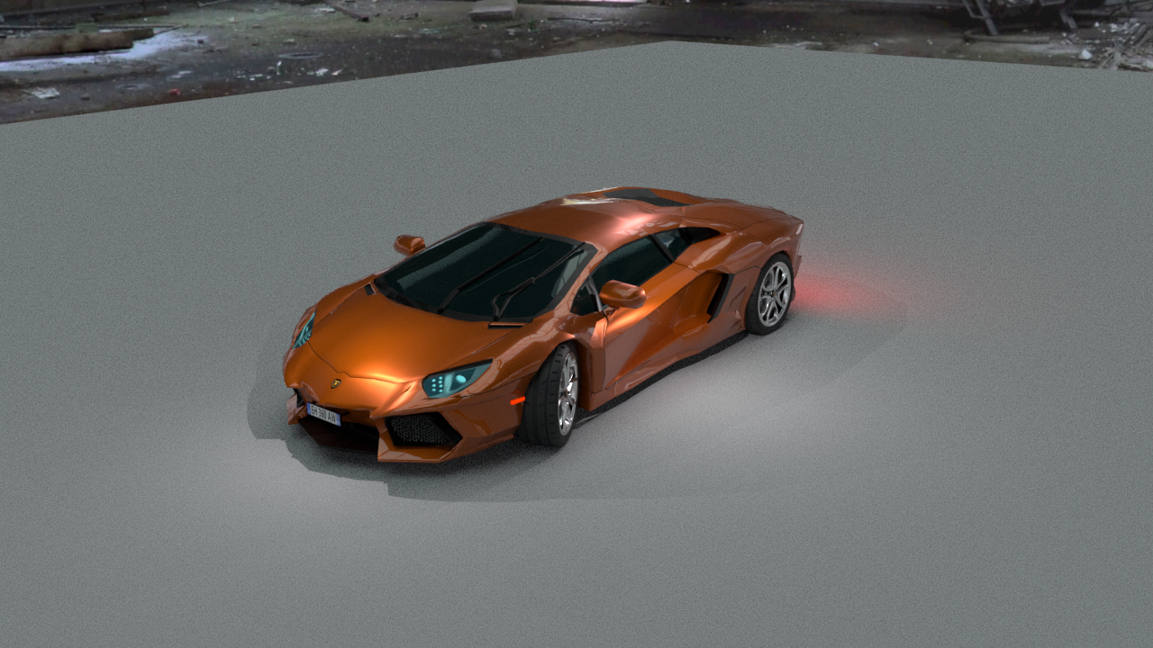
At the beginning of 2018, I tried to figure out something to create for my portfolio. The next step for me would be to create a car, since I had not previously tried it and I felt ready to attempt something more complicated. I have always loved Lamborghini and my favorite is the Aventador. It was not a difficult choice.
For an introduction of the Lamborghini Aventador, I would strongly recommend watching Top Gear’s review of it. This footage, along with some blueprints, has been a massive source of inspiration.
This project has challenged me in many ways, and taught me new essential workflows especially when creating cars. I would lie if I did not say that I made any mistakes along the way, but it was all worth it. Now, I want to finish up this project and continue making cars now that I know how to approach it. I realize I still have a long way to go, but this is better than what I have produced in the past. I will only continue to work harder on these kind of projects to become better. Most importantly, I had fun and it feels good to have found my way back to it.
I would also like to thank my friends Jonte Carrera and Jesper Eriksson for the helpful feedback I have received in order to improve my work.
Arnold Renderer
Most importantly, I had to learn more about the Arnold Renderer. I feel old, but I started out with Mental Ray. Arnold is now the default renderer in Maya. Solid Angle, the creator of Arnold, was acquired by Autodesk in 2016. Arnold is an optimized brute force algorithm (named after the bodybuilder Arnold Schwarzenegger). Global illumination is calculated on every pixel of the frame. Without sampling, it would be more expensive than sampling techniques such as final gathering or irradiance mapping.
The strengths of Arnold are:
Very fast photorealism.
Cross-application compatible.
Much faster than similiar renderers, such as Autodesk RayTracer or ART.
Arnold is an unbiased renderer, it’s more physically accurate. Mental Ray is a biased renderer.
Global and local control over sampling and ray depth, the number of bounces.
In short, greater realism with less effort. But as with all things, there are some limitations to consider:
Limited render to texture. Mental Ray is better here for content-creation for games, no seperate diffuse and specular pass.
No background rendering (batching) or render farms.
Transmissive and hard caustic (light focused by curved surface) is not possible. No photon mapping, no transmissive or refractive caustics.
Rendering
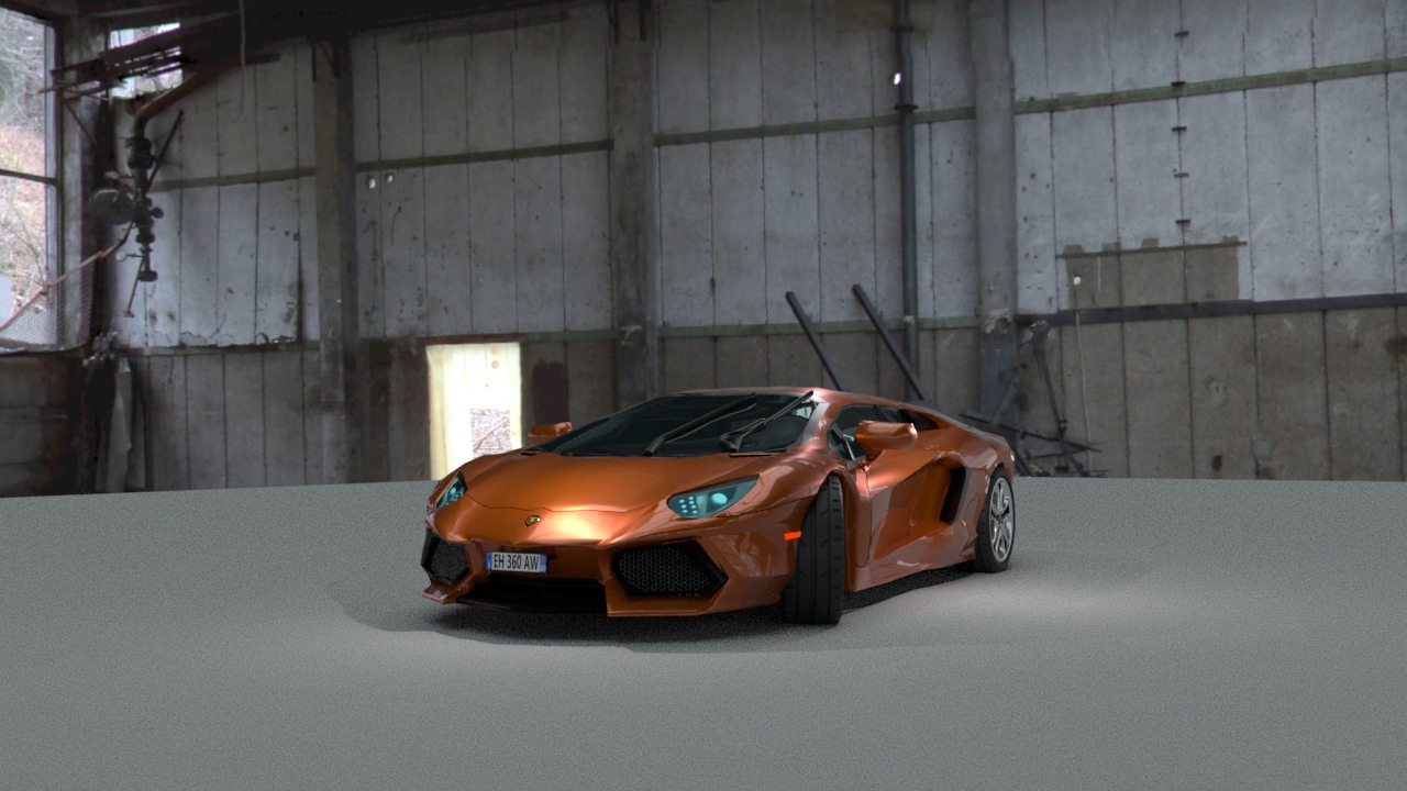
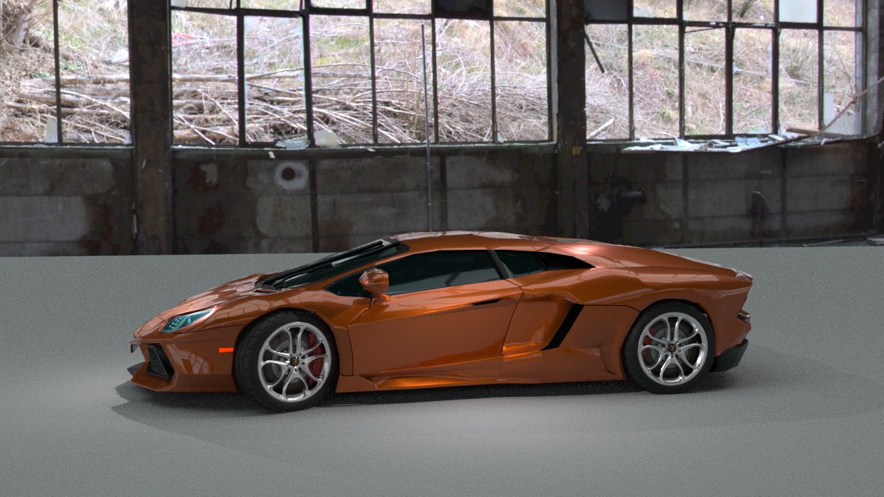
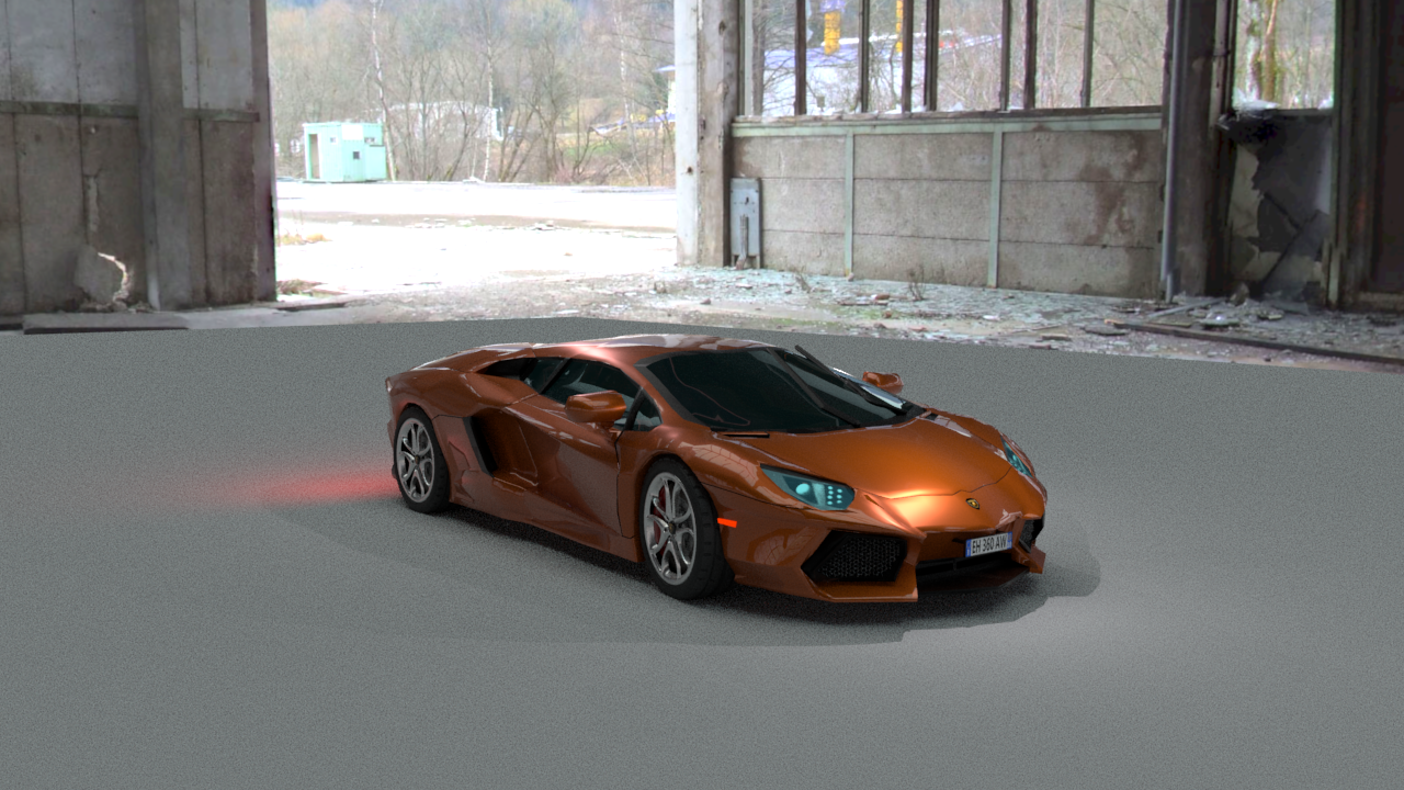
However, the car is not quite done yet. The rest of the week will be focused on fine-tuning the rendering settings to prepare for the final rendering. There has been a lot of tweaking as well with the mesh, as I suffered from some skewed faces that caused me to have weird reflections…some of them are still present but it is much better in comparison to only a few days ago. It is still a bit low poly in some areas as well, most notably around the wheels. The lighting model is not final, I just set up some quick point lights to give the car some highlights on top of the image based lighting.
For our bachelor thesis in development of digital games, Ludvig Arlebrink and I decided to continue with our LOD studies following the pre-study we conducted of Unity’s LOD group component in the beginning of the year. This is only supplementary material for our bachelor thesis, so do not feel like you are missing something if some parts are hard to grasp. It is necessary to have read our paper from the very beginning, but at least you can enjoy the “stunning” graphics! For more supplementary material, see the bottom of the page. The thesis will, hopefully, be available for the public in the coming months. That is, if we actually make it and receive our final grading. For now, nothing is guaranteed.
We had previously thought out many different ideas, staying late at school, frantically drawing on the whiteboard, running the equations, repeatedly bashing our heads into the concrete wall, but no progress. Ludvig was the one coming up with all ideas, I was just tagging along with my curiosity. Sometimes we came up with ideas that were utterly terrible, but sometimes, they left us completely mind blown…only to discover that it had already been done. Damn!
Nothing really stuck with us or seemed to fit the scope of this course. We had started to move away from the LOD pre-study and were curious to take on new techniques, but I think it was the right decision to go back to it. Eventually, Ludvig came up with the idea of image quality-driven LOD selection, which took him a while to explain. The approach felt confusing at first, but then it all made perfect sense.
In this study, we propose an image quality-driven process to choose a LOD combination given a camera position and orientation, and a triangle budget. The metric to assess the quality of the rendered image is the structural similarity (SSIM) index, which is a popular choice in computer science for image comparison for its ability to approximate similarity between images.
The aim of our thesis was to determine the difference in image quality between a custom level of detail pre-preprocessing approach proposed in this paper, and the level of detail system built in the game engine Unity. This is investigated by implementing a framework in Unity for the proposed level of detail pre-preprocessing approach in this paper and designing representative test scenes to collect all data samples. Once the data is collected, the image quality produced by the proposed level of detail pre-preprocessing approach is compared to Unity’s existing level of detail approach using perceptual-based metrics.
Despite that the proposed approach is primarily developed for the personal computer platform (PC), it is more likely to contribute the most to rendering complex scenes on mobile devices. This is because large productions rarely have to be concerned with triangle budgets using the modern day hardware, but mobile devices are running on stricter triangle budgets due to their limited hardware in comparison to the PC. Even so, image quality must still be preserved and maintain a high quality on the triangular meshes even if a lower triangle count is required. That is where the proposed approach differs from the previous DLOD approaches by also taking image quality into account, and not only performance.
Except a few corner cases, such as accidental culling, we managed to maintain similar image quality as Unity’s built-in LOD approach. However, the conclusion is drawn from the experiment that when comparing the SSIM quality of rendered images between Unity’s built-in approach to LOD and the proposed approach, Unity’s built-in approach generally performed better in terms of SSIM.
I would like to thank my friend Ludvig Arlebrink to have been given the opportunity to work with him, this has been a true learning experience and it has really helped my confidence. Last but not least, we would like to thank our supervisor Francisco Lopez Luro for his feedback and guidance throughout the project.
A study of the built-in LOD Group component in Unity carried out by students Ludvig Arlebrink and Fredrik Linde at Blekinge Institute of Technology. This is supplementary material to the full report.
The Unity version used at the time was 2017.3.0f3 (64-bit). We use the Stanford bunny with LODs ranging from 0 to 4 for the experiment. We define five tests: LOD, Crossfade, Dither, No LOD and Empty. Where LOD, is a standard LOD test using the unity LOD group component, without any transitions. Both crossfade and dither also uses the LOD group component but with transitions enabled and set to crossfade. The no LOD does not use the LOD group component and renders the bunny on its maximum LOD. Finally, the empty test is just for reference and is a completely empty scene with a black clear color.
We began the implementation with creating Unity prefabs for each of the tests, except the empty test. For the LOD, crossfade and dither test, we add a LOD group component and for each LOD we add a child gameobject with a mesh renderer component for the LOD mesh. The No LOD prefab only includes a mesh renderer component with no children.
In the beginning of a test, we instantiate 20 bunnies of its corresponding prefab for each axis for a total size of 8000 bunnies. When the test is complete, we destroy all instances of the bunny and repeat this process until all tests have finished executing. At this point the application enters its final stage by running the empty scene test and automatically shuts down afterwards. We created a script for the camera to traverse a path defined by a number of points that the camera interpolates between given a constant speed at all times.